Inline process measurement technology
for the chemical industry
for measuring, controlling and monitoring chemicals
- Optimize production processes
- Improve product quality
- Handling chemicals safely
Fluid.iO is a manufacturer of inline process measurement technology for fluids and a technology supplier for the Chemical industry
We support you with robust measurement technology to meet these metrological challenges:
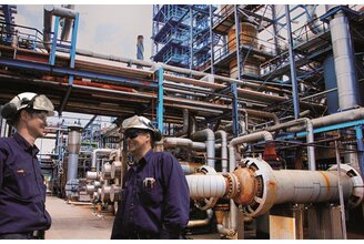
Monitor process conditions
- Temperature and humidity measurement
- Level probes
- Viscosity sensors
- Pressure sensors

monitor chemicals
- Min-Max regulations
- Controlling and dosing fill levels
- Display & evaluation of measurement data
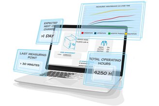
Optimize production
- Avoid defective batches
- earliest detection of changes
- best product quality
Measurable parameters of chemicals with Fluid.iO sensors
Our inline sensors allow you to measure the following process variables in your chemical plant:




Typische Anwendungen unserer Messtechnik in der chemischen Industrie
Lacke & Farben Polymerschmelzen Dosierung & Abfüllung Oil bunkering Asphalt & Bitumen

Paint and varnish manufacturing
fluidio.branch.chemical.section9.chp.titletext
-
Controlling fluctuating media viscosity with inline viscometers
-
fluidio.branch.chemical.section9.chp.list2

Polymerschmelzen
Robuste Sensorik für Hochdruck-, Hochtemperatur- und Schmelzeprozesse in der Kunststoff- und Polymerindustrie.
-
to improve the efficiency of extrusion and polymerization processes
-
stable melt quality & reduction of material loss
-
Continuous inline process measurement technology & precise real-time monitoring of pressure, temperature, level and viscosity
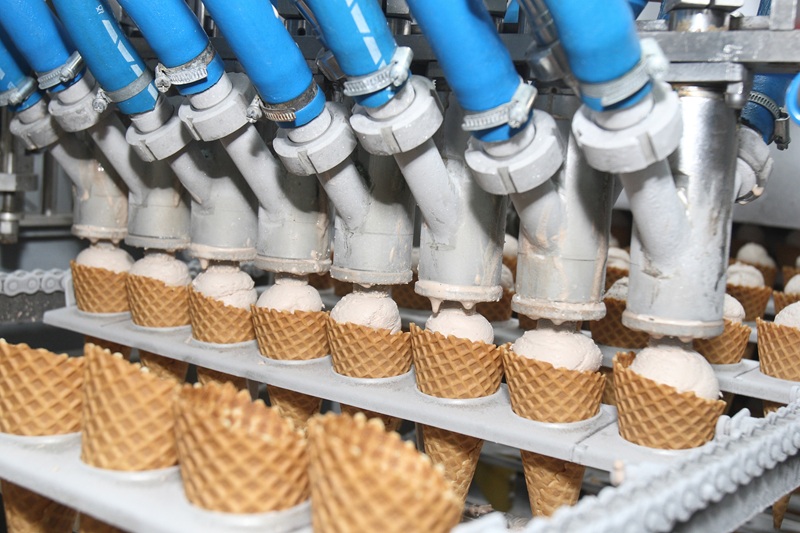
Dosierung & Abfüllung
fluidio.branch.chemical.section9.hydraulics.titletext
-
fluidio.branch.chemical.section9.hydraulics.list1
-
fluidio.branch.chemical.section9.hydraulics.list2
-
fluidio.branch.chemical.section9.hydraulics.list3

Oil bunkering
fluidio.branch.chemical.section9.compressor.titletext
-
fluidio.branch.chemical.section9.compressor.list1
-
fluidio.branch.chemical.section9.compressor.list2
-
fluidio.branch.chemical.section9.compressor.list3

Asphalt & Bitumen
fluidio.branch.chemical.section9.industrial.titletext
-
fluidio.branch.chemical.section9.industrial.list1
-
fluidio.branch.chemical.section9.industrial.list2

fluidio.branch.chemical.section9.marine.titleh2
fluidio.branch.chemical.section9.marine.titletext
-
fluidio.branch.chemical.section9.marine.list1
-
fluidio.branch.chemical.section9.marine.list2
-
fluidio.branch.chemical.section9.marine.list3
Your advantages through precise measurement technology in the chemical industry
In the chemical industry, safety, process stability, and reproducible quality are among the most crucial success factors. Modern sensor technology and process measurement systems from Fluid.iO enable reliable monitoring even under extreme conditions with aggressive media, high accuracy requirements, and stringent regulatory guidelines. This allows for efficient process control, minimized risks, and the safe and economical long-term operation of plants.

In the chemical industry, safe and stable process control is crucial for quality, efficiency and plant protection.
Maximum process reliability
Continuous process monitoring reduces risks and ensures stable production conditions even with aggressive media and critical reactions.
- Stable monitoring of reaction processes
- Detect process deviations early
- Increase plant safety
- Minimize production risks
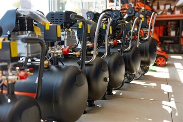
Sensors in the chemical industry must reliably operate with corrosive, toxic and highly reactive media.
Consistency in aggressive media
Robust materials and suitable measuring principles ensure a long service life even under extreme chemical conditions.
- Corrosion-resistant materials
- Reliable measurement of aggressive media
- Long sensor lifespan
- Low maintenance
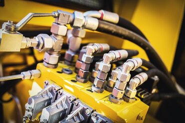
Precise dosing and mixing processes are crucial for product quality and reproducibility of chemical products.
Efficient and precise dosing
Precise measurements enable controlled management of raw material and additive quantities in real time.
- Precise raw material dosage
- Ensuring consistent product quality
- reduce material losses
- Real-time process optimization

Compliance with strict safety and environmental regulations requires reliable monitoring of all critical process parameters.
Safety & legal compliance
Measurement technology supports compliance with standards and protects employees, equipment and the environment.
- ATEX-compliant solutions
- Comply with environmental and safety standards
- Detect leaks early
- Reduce risks for staff
humdity & dew point
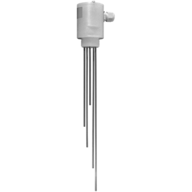
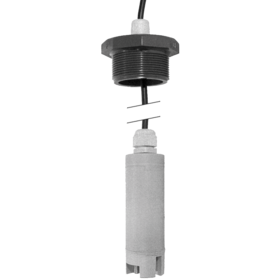
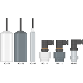
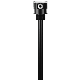
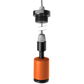
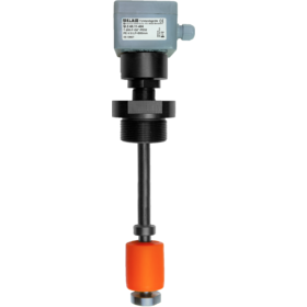
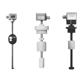
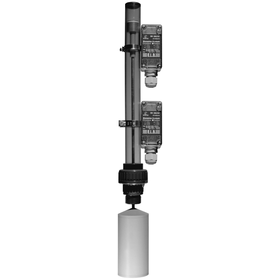
level measurement
flow measurement
process analytics
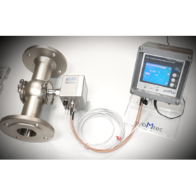
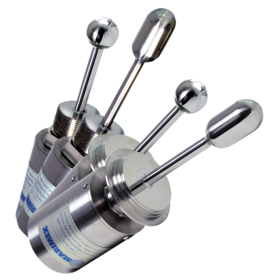
Maintenance-free inline viscosity sensor for precise and reliable real-time measurement of viscosity ...
ViscoScope® VA-300
Maintenance-free inline process viscometer for real-time viscosity measurement
suitable for : fluids
The ViscoScope® sensors are made of high-quality, first-class stainless steel and impress with their ...
Alarm
fluidio.branch.chemical.advantages.title
- fluidio.branch.chemical.advantages.usp1
- fluidio.branch.chemical.advantages.usp2
- fluidio.branch.chemical.advantages.usp3
- fluidio.branch.chemical.advantages.usp4
- fluidio.branch.chemical.advantages.usp5
Nehmen Sie Kontakt mit uns.
Unsere erfahrenen Vertriebsingenieure freuen sich auf Ihre Anfrage!
Vertrieb International
info@fluidio.de +49-6251-8462-0Wir beraten Sie persönlich!

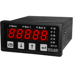
AD-310 : Technische Daten
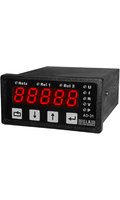
programmable Digital Display
- Universal measurement inputs for current (0(4)...20 mA DC) & voltage 0(2)...10 V DC
- Operation via buttons & 5-digit LED display with display range -19999...32000
- 2 programmable limit switches
Properties
- Protection class EN60529 clamp
- IP 20
- Protection class EN60529 front panel
- IP 65
- Operating temperature
- – 20...+ 60 °C
- nominal voltage
- Weitbereichsnetzteil; 20 V DC ... 230 V AC
- Power consumption
- max. ca. 3 VA
- Output contact
- 2 Schließer / NO
- Switching voltage
- max. 250 V AC, 300 V DC
- Switching current
- max. 3 A , DC min. 30 mA
- Switching capacity
- max. 50W, 100 VA
- Unregulated auxiliary voltage source
- 15...20 V DC / 20 mA
- Display
- LED 14 mm, 5-stellig
- Dimensions
- 96x48x100 mm
- Weight
- ca. 200 g
- Panel cut-out
- H:45+0,6mm, B:92+0,8 mm
Equipment
- Measuring input current
- 0(4)...20 mA DC
- Measuring input voltage
- 0(2)...10 V DC
- Measuring input Potentiometric voltage divider
- 1...100 kΩ
- Display
- LED 14 mm, 5-stellig
- operation
- Folientasten
- Display range
- -19999...32000
- data backup
- EEPROM
- measurement uncertainty
- ±1 % oder ±1 Digit
- analogue output
- 0 (4)...20 mA
Dokumente zum Produkt
 AD-31X Datenblatt
 AD-31X Declaration of Conformity
AD-31X Konformitätserklärung
AD-31X data sheet
Anschlussbild US-100
Betriebsanleitung AD-31X
Produktvarianten
AD-31 - [ 1 ] - [ 2 ] - [ 3 ]
1 Grenzkontakte
- 0 : ohne Grenzkontakte
- 3 : mit 2 Grenzkontakten
2 Versorgungsspannung
- 9 : 20...230 V AC/DC Weitbereichsnetzteil
- 00 : ohne Netzteil
3 Schnittstelle
- 1 : mit RS 485
- 00 : ohne RS 485
DSM2420 : Technische Daten
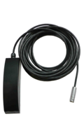
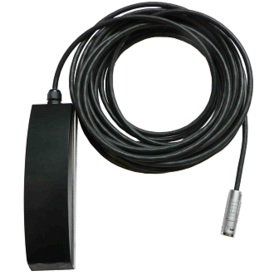
Sensor for simultaneous measuring flow velocity and filling level
- Sensor made of special plastic; resistant to aggressive media
- Mounting in the duct by means of adaptable stainless steel mounting shoes
- Use in EX atmosphere with FDL400 measuring device with integrated Z-barrier
Properties
- Dimensions
- 180 x 48 x 36,5 mm ( L x B x H )
- Weight
- ca. 1,5 kg
- Protection class
- IP68
- Cable length (standard)
- 15 m
- Bending radius
- > 10 x D (Kabeldurchmesser 6,25mm) = > 62,5mm
- Temperature range
- 0°C ... 50°C
- Mounting shoe material
- V2A 1,5mm
Certificates
- EX / ATEX
- IBExU 04 ATEX 1256
Measuring principle
- Flow velocity: Ultrasonic Doppler
- Filling level: Differential pressure
Flow velocity
- Measuring range
- 0,01 - 4 m / s
- Measuring accuracy
- +/- 5 % vom Momentanwert im Kanal
- Temperature drift
- 0,1% / °C ( Meßspanne )
- Temperature drift
- 0,05% / °C ( Nullpunkt )
- Output signal
- 4 - 20 mA
Filling level
- Measuring ranges
- 0 –1 m ; 0 – 2 m ; 0 – 4 m
- Measuring accuracy
- < 0,2% v.E. Summe aus Nichtlinearität, Hysterese und Wiederholbarkeit
- Temperature drift
- 0,005% / °C v.E. Meßspanne
- Temperature drift
- 0,005% / °C v.E. Nullpunkt
- Material
- Al2O3 (96%) aktive Fläche
- Output signal
- 4 – 20 mA
- Zero point
- norm 4 mA ( +/- 3 % )
Dokumente zum Produkt
DSM 2420 Montage- und Betriebsanleitung
DSM 2420 Mounting- & Installation instructions
DSM2420 Declaration of conformity
DSM2420 Konformitätserklärung
Datenblatt DSM2420 Durchfluss Sensor
Durchfluss Messsystem
Flow measuring system
IBExU 04 ATEX 1256 DSM2420
IBExU 04 ATEX 1256 DSM2420
data sheet DSM2420 flow Sensor
EE-24 : Technische Daten
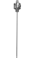
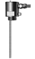
Ex-Electrode-single with integrated safety barrier
- mit integrierter Sicherheitsbarriere
- EG-Baumusterprüfbescheinigung TÜV 09 ATEX 555232
- Elektronik im Anschlußkopf eingebaut & vergossen
Properties
- connection thread
- G 1/2” Standard | G 3/4” | G1”
- Cable
- TPK (Standard) | SIL (Silikon) | FEP (Teflon)
- rod length
- max. 6.000 mm
- Operating pressure
- max. 40 bar
Material
- electrode body
- Edelstahl 1.4571
- Process connection
- Edelstahl 1.4571
- Coating
- PTFE
- electrode rod
- Edelstahl 1.4571
- on request
- Hastelloy C | Tantal
Dokumente zum Produkt
Allgemeine Daten Elektroden
Betriebsanleitung EE-24
Datenblatt EE-24
Declaration of Confomity EE-24
General information electrodes
Konformitätserklärung EE-24
TUEV 09 ATEX 555232
TUEV 09 ATEX 555232
data sheet EE-24
Produktvarianten
EE24 - [ 1 ] - [ 2 ] - [ 3 ] - [ 4 ] - [ 5 ] - [ 6 ] - [ 7 ] - [ 8 ]
1 Anschlußgewinde
- G050 : G1/2”
- G075 : G 3/4”
- G100 : G1"
2 Stabmaterial
- VA : Edelstahl 1.4571
- HC : Hastelloy C
- TA : Tantal
3 Stabdurchmesser
- 4 : 4 mm
- 6 : 6 mm
4 Beschichtung
- TI : teilisoliert PTFE
- VI : vollisoliert PTFE
5 Kabelmaterial
- TPK : Technisch Polymerer Kunststoff
- FEP : Teflon
- SIL : Silikon
6 Kabellänge
- 01 : 1 m
- 02 : 2 m
- XX : Länge in m (bitte angeben)
7 Stablänge
- XX : Länge in mm (bitte angeben)
8 Optional:SIL
- 2 : SIL2
EE-2X : Technische Daten
electrode, multiple for Ex-Zone 0 (Cat. 1)
- Montage innerhalb von Behältern
- EG-Baumusterprüfbescheinigung TÜV 02 ATEX 1796 X
- allgemeine bauaufsichtliche Zulassung Z-65.13-405
Variants
- cable connection on side
- EE-21
- cable connection on top
- EE-22
Properties
- connection
- Edelstahl (1.4571)
- Protection class EN60529
- IP65
- Ex-protection
- TÜV 02 ATEX 1796 X
- Ex protection type
- II 1 G Ex ia IIC T6 bzw. Ex ia IIB T6 / II ½ G Ex ia IIC T6 bzw. Ex ia IIB T6
- connection thread
- G1" | G1¼"
- Cable entry EE-21
- Edelstahl (1.4571)
- Cable entry EE-22
- Kunststoff
- Rod diameter
- 4 mm | 6 mm
- rod length
- max. 6.000 mm
- Operating pressure media side
- max. 40 bar
- Spacer
- ab Länge > 1000 mm je 1 pro 1000 mm
Material
- electrode body
- Edelstahl (1.4571)
- Seal (head)
- Viton
- Seal (media side)
- Viton | PTFE
- Potential equalisation conductor connection
- Edelstahl (1.4571)
- electrode rods
- Edelstahl (1.4571) | Hastelloy C | Tantal
- Coating
- PTFE
Operating temperature
- Category 1 Class T6...T1
- 60 °C
- Category 2 Class T6
- 80 °C
- Category 2 Class T5
- 95 °C
- Category 2 Class T4
- 130 °C (100°C)
- Category 2 Class T3...T1
- 150 °C (100°C)
Dokumente zum Produkt
Allgemeine Daten Elektroden
Betriebsanleitung EE-21 EE-22
Datenblatt EE-21 EE-22
Declaration of Conformity EE-21 EE-22
 Description technique
 Descrizione tecnica
Einstellhinweise
General information
Konformitätserklärung EE-21 EE-22
Setting notes
TUEV 02 ATEX 1796 X
TUEV 02 ATEX 1796 X
Technische Beschreibung
 Technische beschrijving
Z-65.13-405
data sheet EE-21 EE-22
Produktvarianten
EE2 - [ 1 ] - [ 2 ] - [ 3 ] - [ 4 ] - [ 5 ] - [ 6 ] - [ 7 ] - [ 8 ]
1 Typ
- 1 : vollständig Kategorie 1, Kabelanschluss seitlich
- 2 : vollständig Kategorie 1, Kabelanschluss oben
2 Elektrodenanzahl
- 2 : 2 Elektroden bei G1"
- X : 2...4 Elektroden bei G 1¼" (bitte angeben)
3 Anschlussgewinde
- G100 : G 1”
- G125 : G 1¼”
- G150 : G 1½”
4 Stabmaterial
- VA : Edelstahl (.4571)
- HC : Hastelloy C
- TA : Tantal
5 Stabdurchmesser
- 4 : 4 mm
- 6 : 6 mm
6 Beschichtung
- TI : teilisoliert PTFE
- VI : vollisoliert PTFE
7 Stablänge
- X : max. 6.000 mm (bitte angeben)
8 SIL2
- 2 : SIL2
EF2...5 : Technische Daten
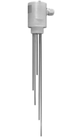
Conductive Electrodes with general approval for constructions
- High chemical resistance
- Use in category 2 (Ex-zone 1) with ER-145…
- Line monitoring for cable short-circuit / cable break
Properties
- Protection class EN60529
- IP 65
- connection thread
- G1" | G1¼" | G1½"
- Union nut
- G2¾" | S 100x8
- Operating temperature PE / PVC
- atmospheric
- Operating temperature PPH
- 90°C
- Operating temperature PTFE
- 100°C
- Operating pressure
- atmospheric
- Resistance value of line monitoring
- 22 kΩ / 100 kΩ
- Spacer form length > 1000 mm
- 1 per 1000 mm
- rod length
- max. 6.000 mm
- Rod diameter
- 4mm | 6 mm
Material
- Screw connection
- PPH | PE | PVC | PTFE
- Sensor rods
- Edelstahl (1.4571), Hastelloy C, Titan, Tantal
- Coating
- PTFE
- ltdata.
Dokumente zum Produkt
Betriebsanleitung ET-410, -420,-421 ...
Betriebsanleitung ET-470
Datenblatt EF2 24...230V
Datenblatt EF2...5
Datenblatt EF3...5
Datenblatt EFV2 24...230V
Datenblatt EFV2 24V
Description technique
Description technique KVU 302.015
Descrizione tecnica
Descrizione tecnica KVU 302.015
Einstellhinweise EF2...5
KVU 302.015 (Schweiz)
Konformitätserklärung Elektroden
Technische Beschreibung EF2...5
Technische Beschreibung KVU 302.015
Technische beschrijving
Z-65.13-405
data sheet EF2 24...230V
data sheet EF2...5
data sheet EF3...5
data sheet EFV2 24...230V
data sheet EFV2 24V
declaration of conformity electrodes
setting notes EF2...5
Produktvarianten
EF - [ 1 ] - [ 2 ] - [ 3 ] - [ 4 ] - [ 5 ] - [ 6 ] - [ 7 ] - [ 8 ] - [ 9 ] - [ 10 ]
1 Elektrodenanzahl
- 2 : 2 Elektroden
- 3 : 3 Elektroden
- 4 : 4 Elektroden
- 5 : 5 Elektroden
2 Verschraubungsmaterial
- PP : Polypropylen (Standard)
- PE : Polyethylen
- PV : Polyvinylchlorid
- PT : Polytetrafluorethylen
3 Stabmaterial
- VA : 1.4571
- HC : Hastelloy C
- TI : Titan
- TA : Tantal
- HC/TA : Tantalspitze mit HC-Grundstab
4 Stabdurchmesser
- 4 : 4 mm
- 6 : 6 mm
5 Elektrodenbeschichtung
- VI : vollisoliert
- TI : ca. 250 mm teilisoliert
6 Anschlussgewinde
- 125 : G1¼”
- 1" : G1” (nur EF2)
- 15" : G1½”
- GF : Überwurfmutter G2¾”
- S2 : Überwurfmutter S100 x 8
7 Kabelbruchwiderstand
- 22 : 22 kΩ
- 100 : 100 kΩ
8 Auswerteelektronik
- ER : Auswertung über Elektrodenrelais
- ET : mit Elektronikteil ET450/ET451 (nur EF2)
9 Stablänge
- XX : bitte angeben (max 6.000 mm)
10 SIL2
- OSIL2 : ohne SIL2
- SIL2 : SIL2
ELH : Technische Daten
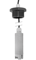
Suspension electrode as leakage probe
- High chemical resistance
- Use in Ex zone 1 (category 2)
- Various diameters
General data
- Protection class
- IP 68
- Probe body material
- PE, PVC, PPH, PVDF
- Diameter probe body
- 15 mm, 25 mm, 40 mm
- Operating temperature
- atmosphärisch
- Operating pressure
- atmosphärisch
- Resistance value of line monitoring
- 22 kΩ / 100 kΩ
Material
- Screw connection
- PVDF
- Cable
- TPK ( PVC Basis)
- on request
- FEP (Teflon), PVC - blau
- cable length
- auf Wunsch (Standard 3 m)
- Material Sensor rods
- Edelstahl (1.4571), Hastelloy B, Hastelloy C, Titan, Tantal, Glas-Kohlestifte
Dokumente zum Produkt
Betriebsanleitung ET-480
Datenblatt ELH
Datenblatt ELH 24...230V
Datenblatt ELH 24V
Declaration of Conformity Electrodes
Description technique
Descrizione tecnica
Einstellhinweise
IBExU1 OATEX1 089
IBExU1 OATEX1 089
IBExU1 OATEX1 089
KVU-Nr. 321.011 (Schweiz)
Konformitätserklärung Elektroden
Technical Description
Technische Beschreibung
Technische Beschrijving
Z-65.40-191
data sheet ELH
data sheet ELH 24...230V
data sheet ELH 24V
setting notes
FDL400 : Technische Daten
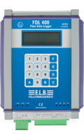
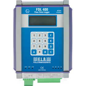
Flow Data Logger
- Wall mounting or DIN rail mounting
- Display of flow velocity, fill level, flow rate, flow volume
- Configurable outputs
Properties
- Housing
- Aluminium
- Protection class
- IP30
- Dimensions
- 197 x 153 x 37,5mm (B x H x T)
- Temperature range
- 0 – 50°C
- Supply voltage
- 24V DC +/-20%
- Power consumption
- 120mA – 220mA
- Reverse polarity protection
- ✓
- Display
- 4x20
Outputs
- analog 0(4)–20mA
- 3x
- digital
- 4x
- fixed for alarm
- 1x
- free configurable
- 3x
display of measured value
- Flow velocity
- Filling level
- flow
- flow rate
Dokumente zum Produkt
Datenblatt FDL400 Durchfluss Datenlogger
Durchfluss Messsystem
FDL400 Declaration of Conformity
FDL400 Konfomitätserklärung
FDL400 Montage- und Betriebsanleitung
FDL400 Mounting & Installation instructions
Flow measuring system
IBExU 14 ATEX 1280X
IBExU 14 ATEX 1280X
data sheet FDL400 flow data logger
HD-1XX : Technische Daten
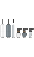
Hydrostatic filling level measurement
- als hydrostatische Einschraub- oder Tauchsonde erhältlich
- hohe Medienbeständtigkeit
- einfache Installation & vielseitige Einsatzmöglichkeiten
Dokumente zum Produkt
Betriebsanleitung HD-10X
Betriebsanleitung HD-11X
Datenblatt HD-10X
Datenblatt HD-11X
Hydrostatic level devices
Hydrostatische Füllstandsgeräte
data sheet HD-10X
data sheet HD-11X
KF25 : Technische Daten
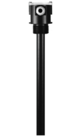
Capacitive level sensors as overfill protection
Properties
- Power supply
- 24 VDC … 230 VAC; max. 2,5 W
- Switching voltage
- 24 VDC … 230 VAC; max. 2,5 W
- Switching current
- max.: 0,12 mA (kurzschlussfest), min.: 1 mA (CMOS Relais)
- Switching capacity
- max.: 2,5 W
- ltdata.Schaltpunkt
- ˂ 10 mm . . . ca. 30 mm
- Sensitivity
- ca. 1pF (Piko Farad), für Flüssigkeiten mit einem ε r ≥ 2 (Petroleum)
- ltdata.Betriebsart
- Ruhestromprinzip
Dokumente zum Produkt
Declaration of Conformity Electrodes
Declaration of Conformity Electrodes EX
Description technique Sonde de fuite type KF25
Descrizione tecnica Sonda di perdita tipo KF25
KVU Schweizer Zulassung für KF25
Technische Beschreibung KF25
Z-65.13-551
Produktvarianten
KF25 - [ 1 ]
1 Variante
- F : Stabversion fest
- V : Stabversion verstellbar
- H : Version hängend mit Kabel
KL25 : Technische Daten
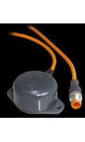
Capacitive leakage probe
Properties
- ltdata.SchutzartnachDINEN60529Sondenkörper)
- IP68
- ltdata.SchutzartnachDINEN60529Stekcer/Dose
- IP65
- ltdata.Leitungstyp
- geeignetes Leitungsmaterial
- ltdata.Leitungslänge
- auf Wunsch
- Operating pressure
- atmosphärisch / max. 2 bar
- ltdata.Medien-undUmgebungstemperaturStandard
- -20 °C ... max. + 80 °C
- ltdata.Medien-undUmgebungstemperaturPVC
- -20 °C ... max. + 60 °C
Connection
- Housing
- Polyester / Polycarbonat / Aluminium
- ltdata.Kabelanschluss
- Plug
Dokumente zum Produkt
Declaration of Conformity Electrodes
Declaration of Conformity Electrodes EX
Description technique de la sonde de fuite type KL25
Descrizione tecnica della sonda di perdita tipo KL25
KVU Zertifikat (Schweizer Zulassung) für KL25
Technische Beschreibung Leckagesonde Typ KL25
Z-65.40-552
Produktvarianten
KL25 - [ 1 ] - [ 2 ] - [ 3 ] - [ 4 ]
1 Ausführung
- F : Stabversion fest (Ex-Version)
- V : Stabversion verstellbar (Ex-Version)
- K : Kabelversion hängend, mit Sondenkörper Ø 16 mm (Nicht-Ex)
- P : Kabelversion stehend, mit PVC-Sondenkörper ca. Ø 50 mm (Nicht-Ex)/L
2 Sondenmaterial
- PE : PE
- PVC : PVC (Kabelversion stehend, mit PVC-Sondenkörper ca. Ø 50 mm)
- XX : optional Kundenwunsch
3 Anschluss
- ST : Steckeranschluss (Standard bei Version fest + verstellbar sowie Version stehend, nicht bei Version hängend)
- AD : optional Anschlussdose (Standard bei Version hängend)
- KS : optional Kabelschwanz
- XX : optional Kundenwunsch
4 Verschraubung
- OH : ohne
- G1 : G 1“
- XX : optional Kundenwunsch
MKL : Technische Daten
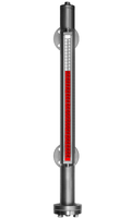
Magnetic Flap Indicator
- Continuous evaluation of the liquid level
- Insensitive to vibration
- Functions without auxiliary power
Properties
- connection
- Flansch ab DN 15
- Material
- rostfreier Edelstahl, PVC, PPH, PVDF
- Material flange
- Edelstahl 1.4571, C22.8
- Material Float
- Edelstahl, Titan, PVC, PPH, PVDF
- Number of contacts
- beliebig
- Contact load
- max 10 VA, max 230 V AC
- Display length
- max. 6m
Operating temperature
- PTFE seal
- max. 150 °C
- Stainless steel: Klingerit seal
- max. 200 °C
- PVC
- max. 60 °C
- PPH
- max. 90 °C
- PVDF
- max. 130 °C
Stainless steel float
- Weight
- ~ 300 g
- Dimensions
- Ø 52 x 270
- Operating pressure
- 16 bar
- media density
- ρ ≥ 0,70 g/cm³
Stainless steel float
- Weight
- ~ 320 g
- Dimensions
- Ø 52 x 270
- Operating pressure
- 40 bar
- media density
- ρ ≥ 0,75 g/cm³
Titanium float
- Weight
- ~ 180 g
- Dimensions
- Ø 52 x 150
- Operating pressure
- 16 / 40 bar
- media density
- ρ ≥ 0,73 g/cm³
PVC float
- Weight
- ~ 331 g
- Dimensions
- Ø 52 x 250
- Operating pressure
- 6 bar
- media density
- ρ ≥ 0,8 g/cm³
PPH float
- Weight
- ~ 283 g
- Dimensions
- Ø 52 x 250
- Operating pressure
- 6 bar
- media density
- ρ ≥ 0,69 g/cm³
PVDF float
- Weight
- ~ 352 g
- Dimensions
- Ø 52 x 250
- Operating pressure
- 6 bar
- media density
- ρ ≥ 0,85 g/cm³
Dokumente zum Produkt
Datenblatt MKL
EX9 06 07 43146 001
ISD-22-25-0107
ISF-22-21-0016
Konformitätserklärung EX
Konformitätserklärung PTFE Ex
MKL Betriebsanleitung
data sheet MKL
Produktvarianten
MKL - [ 1 ] - [ 2 ] - [ 3 ] - [ 4 ] - [ 5 ] - [ 6 ] - [ 7 ]
1 Material
- 3 : Edelstahl 1.4571 (PN 16); Flansche seitlich
- 5 : Edelstahl 1.4571 (PN 16); Flansche oben/unten
- 6 : Edelstahl 1.4571 (PN 40); Flansche seitlich
- 7 : PVC (PN 6)
- 8 : PPH (PN 6)
- 9 : PVDF (PN 6)
2 Anschlussflansch
- 00 : wie Materialauswahl
- V4A : Edelstahl 1.4571
- C22 : C 22.8 (nur bei 3, 5, 6)
3 Prozessanschluss
- DN 15 : DN 15
- DN 20 : DN 20
- DN 25 : DN 25
- DN 32 : DN 32
- DN 40 : DN 40
- DN 50 : DN 50
- FL : Flanschkugel
- 99 : Sonderausführungen nach Kundenwunsch (bitte angeben)
4 Schwimmer
- 1 : Edelstahl
- 2 : Titan
- 7 : PVC
- 8 : PPH
- 9 : PVDF
5 Ablassschraube
- A : ½” (Standard)
6 Anzeige
- 0 : ohne Anzeigeschiene
- 1 : Aluminiumschiene mit Makrolonsichtfenster
7 Mittenentfernung
- L : Standard L-Min = 500mm
- L-99 : Andere (bitte angeben)
MTA : Technische Daten
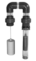
Mechanical tank level indicator
- simple, proven indication principle for containers
- suitable for water-polluting, non-flammable liquids
- Requires no energy supply
Properties
- Tank connection
- Flansch ab DN 80 (Sonderanschlüsse auf Wunsch)
- Material
- siehe Maßbild
- Material Tube
- PVC, transparent | Ø 50 x 1,8 | Ø 63 x 3,0
- Operating temperature
- –20...+60 °C
- Operating pressure
- atmosphärisch
Material Float
- PPH
- Ø 70 mm 460 g
- PVC
- Ø 70 mm 455 g
- PPH
- Ø 40 mm 370g
- PE
- Ø 70 mm ca. 450 g
Material Rope
- PPH
- (rot, Ø 2 mm) ~ 2 g/m
- Polyester
- (bunt, Ø 2 mm) ~ 4 g/m
- PTFE
- (weiss, Ø 3 mm) ~ 10 g/m
Dokumente zum Produkt
Data Sheet MTA
Datenblatt MTA
MTA Declaration of Conformity
MTA Konformitätserklärung
Produktvarianten
MTA - [ 1 ] - [ 2 ] - [ 3 ] - [ 4 ]
1 Außendurchmesser
- DA50 : Ø 50 mm bis 6m
- DA5012 : Ø 50 mm bis 12m
- DA5016 : Ø 50 mm bis 16m
- DA63 : Ø 63 mm bis 6m
- DA6312 : Ø 63 mm bis 12m
- DA6316 : Ø 63 mm bis 16m
2 Seilsicherung
- 0 : ohne Seilsicherung
- S : mit Seilsicherung
3 Seil
- PP : Polypropylen (rot, Ø 2 mm)
- PO : Polyester (bunt, Ø 2 mm)
- PTFE : Polytetrafluorethylen (weiß, Ø 3 mm)
4 Schwimmer
- PP : Polypropylen Ø 70 mm
- PE : Polyethylen Ø 70 mm
- PV : Polyvinylchlorit Ø 70 mm
- 40 : Polypropylen Ø 40 mm
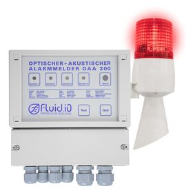
OAA-300 : Technische Daten
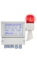
Alarm Indicator (Measuring Transducer) with general approval for construction
- Internal acoustic signal and optic signal Outputs
- Available with 1 to 4 channels
- Integrated monitoring device
Properties
- Protection class EN60529
- IP 65
- Operating temperature
- – 20…+60 °C
- Storage temperature
- – 30…+80 °C
- Sensitivity
- bei konduktiver Messung: 3, 10, 30, 100kΩ
- Dimensions
- 170 x 190 x 85 mm
- Weight
- ca. 0,8 kg
Control circuits
- Open circuit voltage
- max. 10 V DC
- Short-circuit current
- max. 10 mA
- Switching delay
- ca. 0,5 s
Power supply
- nominal voltage
- 230 V AC (optional 24, 115, 240 V AC 24 V DC
- Nominal frequency
- 48...62 Hz
- Power consumption
- max. 3 W/VA
Output
- Switching voltage
- max. 250 V
- Switching current
- max. 3 A
- Switching capacity
- max. 500 VA | max. 50 W
- Volume
- 75 dB
Dokumente zum Produkt
Betriebsanleitung OAA-300 1...4
Betriebsanleitung OAA-300 Vibration
Datenblatt OAA-300
Einstellhinweise OAA-300
Manual OAA-300 1...4
Manual OAA-300 1MOhm
Manual OAA-300 Vibration
OAA-300 Declaration of Conformity
OAA-300 Handbuch 1MOhm
OAA-300 Konformitätserklärung
SIL2 OAA-300
Setting notes OAA-300
Z-65.11-404 Prüfbescheinigung
Z-65.11-404 Technische Beschreibung
Z-65.13-405 Prüfbesheinigung
Z-65.13-405 Technische Beschreibung
data sheet OAA-300
Produktvarianten
OAA-300 - [ 1 ] - [ 2 ] - [ 3 ]
1 Ausführung
- 1 : Einkanal
- 2 : Zweikanal
- 3 : Dreikanal
- 4 : Vierkanal
2 Versorgungsspannung
- ohne Angabe : 230 V AC
- 0 : 24 V DC
- 1 : 24 V AC
- 7 : 240 V AC
- 8 : 115 V AC
3 Signalgeber
- ohne Angabe : keine Hupe
- H : zusätzliche Hupe mit Rundumleuchte
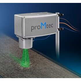
OMC 2500 : Technische Daten
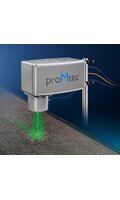
Online Moisture Control
- digital noise filtering
- pre-programmed algorithms and calibrations
- integrated contamination detector for the measuring window
Properties
- Housing
- NEMA4/ IP65
- ltdata.Eingangsspannung
- 80 - 260 V AC (50 Hz/60 Hz), 24 V DC
- measuring resolution
- 16-bit
tdata.Ausgangssignal
- Standard
- Optional
- ltdata.RS232/485
- Devicenet
- ltdata.EthernetTCP/IP
- Profibus / Profinet
- ltdata.EthernetUDP
- Modbus
- ltdata.3x4...20mA
- Ethernet/IP
Dokumente zum Produkt
Produktübersicht Inline Konzentrationsmessung
product overview inline concentration measurement
QFS-12 : Technische Daten
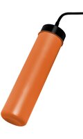
Two-Point Float-Switch
- High chemical resistance
- Suitable for use in liquids with different densities
- Small dimensions for installation through 1”
Properties
- Protection class EN60529
- IP68
- Side installation
- PVC-Stopfbuchsverschraubung G 2”
- Installation from above
- PVC-Stopfbuchsverschraubung G 2”
- Operating pressure
- max. 2 bar
- Contact
- Wechselkontakt
- Switching voltage
- 4....250 V AC / DC
- Switching current
- 1mA.....1A
- Switching capacity
- 60W/VA
- media density
- ρ ≥ 0,9 g/cm³ bis ρ ≥ 0,8 g/cm³
- Material Float
- Polyethylen
Cable
- TPK
- PVC Basis
- TPKV
- PVC Basis verstärkt
- PUR
- Polyurethan
- NEO
- Neopren
- SIL
- Silikon
- FEP
- Teflon
- AEM
- Ethylen-Acrylat-Kautschuk
Operating temperature
- TPK(V), NEO, AEM
- max.+60 °C
- PUR
- max.+70 °C
- FEP, SIL
- max.+80 °C
Dokumente zum Produkt
Betriebsanleitung QFS-12
Datenblatt QFS-12
Declaration of Conformity
Manual QFS-12
QFS-12 Konformitätserklärung
data sheet QFS-12
Produktvarianten
QFS-12 - [ 1 ] - [ 2 ] - [ 3 ] - [ 4 ]
1 Kontakt
- W : Wechsler
2 Schwimmermaterial
- PE : Polyethylen
3 Kabelmaterial
- TPK : PVC Basis
- TPKV : PVC Basis verstärkt
- PUR : Polyurethan
- NEO : Neopren
- SIL : Silikon
- FEP : Teflon
- AEM : Ethylen-Acrylat-Kautschuk
4 Kabellänge
- 01 : 1m
- 02 : 2m
- XX : Länge in m (bitte angeben)
T-200.L : Technische Daten
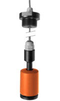
Leakage probes with general building authority approval
- Approved for liquids hazardous to water
- High chemical resistance
- Interference-free measurement
Dokumente zum Produkt
Declaration of conformity for magnetic immersion probes
Description technique
Descrizione tecnica
Einstellhinweise
Konformitätserklärung Magnettauchsonden
SIL Zertifikat
Schweizer Zulassung KVU-Nr. 321.008
Setting instructions
Sicherheitshinweis
Technical description
Technische Beschreibung
Z-65.40-153
T200.F : Technische Daten
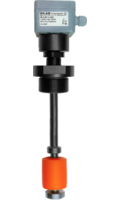
Overfill protection for containers
- with general approval for construction Z-65.11-404
- Low system costs
- High chemical resistance
Connection
- Polyester junction box
- Aluminum housing
- Polyethylene connection head
- Cable
- Plug
Properties
- Protection class EN60529
- IP 65
- connection thread
- G 1", G 1¼", G 1½", G2", G3”
- Union nut
- G 2¾", S 100x8
- Guide tube length
- max. 6 m
- Operating pressure
- Max. 20 bar
- media density
- ρ ≥ 0,6 g/cm³
- Switching hysteresis
- typ. 2 mm
- Switching point tolerance
- max. 2 mm
- Operating temperature
- atmosphärisch
- PP
- max. 90°C
Resistance value
- Operational readiness
- ca. 1 kΩ
- overfill alarm
- ca. 12 kΩ
- Switching time
- ca. 20 ms
- ltdata.
Dokumente zum Produkt
Allgemeine Daten Teil 1 Magnettauschsonden T-20...F
Allgemeine Daten Teil 2 Magnettauschsonden T-20...F
Datenblatt T200.F
Datenblatt T200.F T208.F 24V
Datenblatt T203.FT204.FT204/0.F
Declaration of conformity for magnetic immersion probes
Declaration of conformity for magnetic immersion probes EX
Description technique KVU 302.009
Description technique Z-65.11-404
Descrizione tecnica KVU 302.009
Descrizione tecnica Z-65.11-404
Einstellhinweise
Konformitätserklärung Magnettauchsonden
Konformitätserklärung Magnettauchsonden EX
SIL1 SIL2
Schwizer Zulassung KVU-Nr. 302.009
Setting notes
Sicherheitshinweise
TUEV 02 ATEX 1795 X
TUEV 02 ATEX 1795 X
Technical Description Z-65.11-404
Technische Beschreibung KVU-Nr. 302.009
Technische Beschreibung Z-65.11-404
Technische beschrijving Z-65.11-404
Z-65.11-404
data sheet T200.F
data sheet T200.F T208.F 24V
data sheet T203.FT204.FT204/0.F
general information part 1 immersible magnetic probe T-20...F
general information part 2 immersible magnetic probe T-20...F
TK-30X : Technische Daten
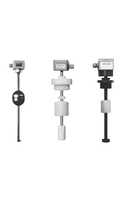
Liquid Level Measuring Instruments Series
- Independent of - Pressure, - Temperature, - Foam, - Conductivity, - Dielectric
- The output signal is proportional to the fill level and independent of the container shape
- Free selection of limit values in the entire measuring range of the probes
Properties
- connection
- Polyesterdose | Aluminiumdose | Stecker nach DIN 43650
- connection thread
- G 3/8”, G 1/2”, G 1”, G 1 1/2”, G 2”, G 3”
- connection cable
- LiYY max. 80 °C | Silikon max. 130 °C
- Sliding tube length
- max. 6000 mm
- Operating temperature
- max. +60...+130 °C | min. –20...–10 °C je nach Ausführung
- Operating pressure
- max. 20 bar je nach Ausführung
- media density
- siehe Schwimmerdaten
- Viscosity
- < 100 cp
- Switching hysteresis
- ca. halbe Auflösung
- Resolution
- 7,5 mm, 10 mm, 15 mm, 20 mm oder 1 %, 2 %, 5 % je nach Ausführung
- Total resistance
- ca. 5 kΩ
- Measuring voltage
- max. 24 V
- Measuring current
- max. 5 mA
Dokumente zum Produkt
Allgemeine Daten TK30x EX I
Allgemeine Daten TK30x EX II
Allgemeine Daten TK30x I
Allgemeine Daten TK30x II
Beiblatt Betriebsanleitung TK-30x...Ex
Betriebsanleitung TK-30x...Ex
General data TK30x EX I
General data TK30x EX II
General data TK30x I
General data TK30x II
TK-30X Declaration of Conformity
TK-30X Declaration of Conformity EX
TK-30X Déclaration de conformité
TK-30X Déclaration de conformité EX
TK-30X Konformitätserklärung
TK-30X Konformitätserklärung EX
TUEV 02 ATEX 1795 X
TUEV 02 ATEX 1795 X
Produktvarianten
TK30 - [ 1 ] - [ 2 ] - [ 3 ] - [ 4 ] - [ 5 ] - [ 6 ] - [ 7 ] - [ 8 ] - [ 9 ]
1 Rohrdurchmesser
- 0 : Rohr Ø 16 mm
- 1 : Rohr Ø 15 mm
- 2 : Rohr Ø 12 mm
- 7 : Rohr Ø 15 mm (Bypass)
- 8 : Rohr Ø 20 mm
- 9 : Rohr Ø 18 mm
2 Rohrmaterial
- PE : Polyethylen
- PP : Polypropylen
- PV : Polyvinylchlorid
- VA : Edelstahl 1.4571
- MS : Messing
- PT : Edelstahl, Rohr PTFE-beschichtet
3 Gewinde
- I3/8” : G 3/8” für Innenmontage
- I1/2” : G 1/2” für Innenmontage
- I1” : G 1” für Innenmontage
- A1/2” : G 1/2” für Außenmontage
- A1” : G 1” für Außenmontage
- A11/4” : G 1 1/4” für Außenmontage
- A11/2” : G 1 1/2” für Außenmontage
- A2” : G 2” für Außenmontage
- A3” : G 3” für Außenmontage
- S : Sonderwunsch (bitte angeben)
4 Ausführung
- ohne Angabe : fest
- V : verstellbar (nur bei Außengewinde)
5 Schwimmerausführung
- 3 : Kugel Edelstahl 52 mm Ø
- 4 : Kugel Edelstahl 62 mm Ø
- 5 : Oval Schwimmer Edelstahl 80 mm Ø
- 6 : Oval Schwimmer Edelstahl 94 mm Ø
- 7 : Kugel Edelstahl 105 mm Ø
- 9 : Zylinder Edelstahl 44 mm Ø
- 10 : Zylinder PE 52 mm Ø
- 11 : Zylinder PE 78 mm Ø
- 12 : Zylinder PE 71 mm Ø
- 14 : Zylinder PP 52 mm Ø
- 15 : Zylinder PP 78 mm Ø
- 16 : Zylinder PTFE 80 mm Ø
- 17 : Zylinder PVC 78 mm Ø
- 18 : Zylinder PVC 55 mm Ø
6 Anschluss
- PO : Polyesterdose
- AA : Aluminiumdose
- ST : 3fach-Stecker
- LY : __ mm Kabel LiYY (Standard 1000 mm)
- SI : __ mm Kabel Silikon (Standard 1000 mm)
- GF : Überwurfmutter 2¾”
- :
7 Rohrlänge
- R : __mm
8 Auflösung
- 7,5 : 7,5 mm
- 10 : 10 mm
- 15 : 15 mm
- 20 : 20 mm
- 1% : 1% (Ausgang 4..20 mA eingebaut in Polyester oder Aluminiumanschlussdose)
- 2% : 2% (Ausgang 4..20 mA eingebaut in Polyester oder Aluminiumanschlussdose)
- 5% : 5% (Ausgang 4..20 mA eingebaut in Polyester oder Aluminiumanschlussdose)
9 Zubehör
- ohne Angabe : ohne Messumformer
- M : mit Messumformer TK-101 Ausgang 4...20 mA, 24 V DC
TOF 1500 : Technische Daten
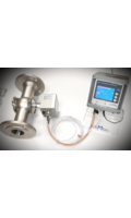
Inline Concentration Control
- Precise concentration measurement
- reliable and continuous analysis directly within the process
- Measurement principle of time of flight
Properties
- ltdata.tba
Dokumente zum Produkt
Produktübersicht Dichte / Konzentrationsmessung
product overview density concentration measurement
TRM-100 : Technische Daten
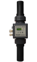
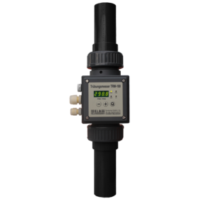
Turbidimeter (0...1.000 FNU or 500...4.000 FAU)
- Measurement of "turbidity" is carried out using the scattered light and transmitted light method
- The turbidimeter works as a stand-alone system.
- Continuous turbidity measurement with 1 freely adjustable changeover contact
Properties
- Operating pressure
- max. 10 bar @ 20 °C | max. 2,5 bar @ 60 °C
- Measuring range
- 500...4.000 FNU / FAU
- Measuring accuracy
- +/-5 %
- Mounting position
- horizontal
- Process connection
- DN 20 | DN 40
- Flange connection
- >= DN 20
- number of senders
- 2
- number of receivers
- 1
Material
- Seal
- EPDM | optional FPM (Viton)
- Process connection
- PVC | PPH
- Measuring tube
- Borsilikatglas mit Nano Beschichtung
Input
- Power supply
- 18...30 V DC
- Power consumption
- < 2 W
Output
- Output contact
- 4...20 mA
- Switching delay (adjustable)
- 1...10 s
- Protection class
- IP 65
- Switching voltage
- max. 250 V AC | max. 115 V DC
- Switching current
- max. 3 A
- Switching capacity
- max. 500 VA, 60 Watt
- Potential-free changeover contact
- 1 @ 1...10 s
Dokumente zum Produkt
Kurzübersicht Trübungsmessung
TRM-100 Data sheet
TRM-100 Datenblatt
TRM-100 Declaration of Conformity
TRM-100 Handbuch
TRM-100 Konformitätserklärung
TRM-100 fiche technique
TRM-100 manual
Turbidity measurement
Produktvarianten
TRM-100 - [ 1 ] - [ 2 ] - [ 3 ] - [ 4 ] - [ 5 ]
1 Material
- PV : PVC (polyvinyl chloride) standard
- PP : PPH (Polypropylene)
2 Measuringrange
- 1 : 500...1.000 FNU/FAU
- 2 : 500...2.000 FNU/FAU
- 3 : 500...4.000 FNU/FAU
- 4 : 1...50 FNU/FAU(Sonder)
- 5 : 1...50 0FNU/FAU
- 6 : 1...100FNU/FAU
- 7 : 1...200FNU/FAU
- 8 : 1...300FNU/FAU
- 9 : 1...400FNU/FAU
3 Connection
- DN20 : DN 20 PN 10
- DN40 : DN 40 PN 10
4 Flange
- FL20 : Flange DN 20 PN 10
- FL25 : Glange DN 25 PN 10
5 Sealing
- without specification : EPDM
- VI : Viton ®
ÜTA-32 : Technische Daten
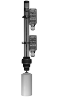
Overfuelling indicator
- Direct indication of the liquid level
- used for level measurement in open and closed tanks
- Level control is steplessly adjustable
Properties
- connection
- G 1” (andere Gewinde auf Anfrage)
- max.length guide tube
- siehe Diagramm
- Operating temperature
- atmosphär. Bedingungen
- Operating pressure
- atmosphär. Bedingungen
- media density
- siehe Eintauchtiefe
- Number of contacts
- beliebig
- Contact load
- max. 10 VA, max. 230 V AC
- Length
- max. 1750 mm
Material
- Sight tube
- PVC transparent
- connection
- PVC-Verschraubung mit PTFE-Stangenführung
- Guide rod
- Edelstahl, Titan, Hastelloy B, Hastelloy C oder PVCRohr
- float
- PE / PP
Dokumente zum Produkt
Data sheet UTA
Datenblatt Übertankanzeiger ÜTA
Handbuch ÜTA
ÜTA Declaration of Conformity
ÜTA Konfomitätserklärung
Produktvarianten
ÜTA 32 - [ 1 ] - [ 2 ] - [ 3 ]
1 Float
- 63 :
- 90 :
2 Guide-rod
- 00 : Stainless steel 1.4571
- HB : Hastelloy B
- HC : Hastelloy C
- TI : Titanium
- PV : PVC
3 Length
- XX : Length in mm (please specify)
ViscoScope® VA-100 : Technische Daten
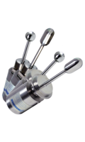
Inline Viscometer
- Reproducible measurement of viscosity in real time
- cavity free installation (CIP / SIP capable)
- Maintenance-free measuring instrument
Properties
- Material
- 1.4571 / 1.4404 (316Ti / 316L)
- Protection class
- IP65
- Process temperature
- -10°C … +130°C | (integriertes Pt100 im Messfühler)
- max. process pressure
- Vakuum ... 64 bar
- Process connections
- NPT | M48 | Varivent® | Tri-Clamp
- Cable length sensor - transmitter
- Max. 1.000 Meter
- max. flow velocity
- 5 m / sec
- Ex approval
- II 1/2G Ex ia IIC T6...T3 Ga/Gb | (optional)
Sensor types
- Sphere
- VA-100B
- Cylinder
- VA-100C
Repeatability
- VA-100B
- ± 0,5% | ± 1 Digit
- VA-100C
- ± 0,3% | ±1 Digit
Measuring ranges
- VA-100C
- 0,1 - 2.500 mPa·s x g/cm³
- VA-100B
- 10 - 25.000 mPa·s x g/cm³
Probe dimensions
- VA-100C
- Ø 32 x 145 mm
- VA-100B
- Ø 32 x 120 mm
installation positions
- Reservoir
- tanks
- Pipe
- flow cell
- Installation is position-independent
Dokumente zum Produkt
Anwendung Kunstharzbeschichtung
Anwendung Schleifstifte
Anwendung Stahlstifte
Anwendung Weichgelantine
Application Grinding Pins
Application Marking Steel
Application soft gelantine
Applikation Resin Coating
Betriebsanleitung ViscoScope alle Sensoren
Datenblatt ViscoScope VA-100
Handbuch ATEX - IECEx - alle Sensoren
IECEx TUR 14.0040X
Manual ATEX - IECEx - all Sensors
Manual ViscoScope all sensors
TUEV 14 ATEX 7603 X
VA-100 Declaration of Conformity
VA-100 Konformitätserklärung
ViscoScope CSA certificate
ViscoScope Vikositätssensoren
ViscoScope Viscosity Measurement
Viscositätsmessung mit ViscoScope
data sheet ViscoScope VA-100
overview ViscoScope viscosity sensor
Produktvarianten
VA-100 - [ 1 ] - [ 2 ] - [ 3 ] - [ 4 ] - [ 5 ]
1 Viscosity
- C : 0,1 - 2.500 mPa·s x g/cm³
- B : 10 - 25.000 mPa·s x g/cm³
2 Temperature
- LT : -40...130 °C
3 Process-Connection
- N : NPT
- V : Varivent®
- T : Tri-Clamp
- S : Special flange Ø 80 x 20 mm for flow cell DZ101
4 Material
- VA : 1.4571/1.4404 (316Ti/316L)
5 Ex-Area
- Ex : II 1/2G Ex ia IIC T6...T3 Ga/Gb
- 00 : without Ex-approval
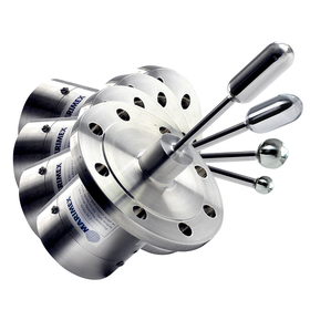
ViscoScope® VA-300 : Technische Daten
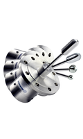
Maintenance-free inline process viscometer for real-time viscosity measurement
- for very low & high viscosities, temperatures & pressures
- Maintenance-free measuring instrument
- Chemicals, petrochemicals, food, pharmaceuticals and cosmetics
Properties
- Protection class
- IP65
- Material
- 1.4571 / 1.4404 (316Ti / 316L)
- Process temperature
- -40°C … +450°C
- Process pressure
- Vakuum ... 450 bar
- Process connections
- DIN Flansch | ANSI Flansch | NPT | Varivent® | Tri-Clamp
- Cable length sensor - transmitter
- max. 1.000m
- max. flow velocity
- 10 m / sec
- Ex approval
- (optional) II 1/2G Ex ia IIC T6...T3 Ga/Gb
- Material (optional)
- Hastelloy C22, Duplex 2205, Teflon
Sensor types
- big cylinder
- VA-300L
- small cylinder
- VA-300M
- Sphere
- VA-300H
- small sphere
- VA-300X
Measuring range
- VA-300L
- 0,1 - 2.500 mPa·s x g/cm³
- VA-300M
- 1 - 25.000 mPa·s x g/cm³
- VA-300H
- 0,01...250 Pa·s x g/cm³
- VA-300X
- 0,1...2.500 Pa·s x g/cm³
Probe dimensions
- VA-300L
- Ø 32 x 190 mm
- VA-300M
- Ø 32 x 165 mm
- VA-300H
- Ø 32 x 130 mm
- VA-300X
- Ø 19 x 115 mm
Dokumente zum Produkt
Allgemeine Daten ViscoScope
Anwendung Kunstharzbeschichtung
Anwendung Schleifstifte
Anwendung Stahlblech markieren
Anwendung Weichgelantine
Application Resin Coating
Application grinding pins
Application marking steel
Application soft gelantine
Betriebsanleitung ViscoScope alle Sensoren
Data sheet VA-300
Datenblatt VA-300
Handbuch ATEX - IECEx - alle Sensoren
IECEx_TUR_14.0040X
Manual ATEX - IECEx - all Sensors
Manual ViscoScope all sensors
Overview ViscoScope
TUEV 14 ATEX 7603 X
VA-300 Declaration of Conformity
VA-300 Konformitätserklärung
ViscoScope CSA certificate
ViscoScope Viscosity Measurement
Viscositätsmessung mit ViscoScope
Produktvarianten
VA-300 - [ 1 ] - [ 2 ] - [ 3 ] - [ 4 ] - [ 5 ] - [ 6 ]
1 Viscosity
- L : 0,1...2.500 mPas* g/cm³
- M : 1...25.000 mPas* g/cm³
- H : 0,01...250 Pas* g/cm³
- X : 0,1...2.500 Pas* g/cm³
- S : application specific
2 Temperature
- LT : -40…130 °C
- ST : -40…300 °C
- HT : -40…450 °C
3 Process-Connection
- DIN : Flansch gemäß EN 1092-1, bitte Abmessungen angeben
- ANSI : Flansch gemäß ASME B16.5, bitte Abmessungen angeben
- N : NPT
- V : Varivent®
- T : Tri-Clamp
4 Material
- VA : Edelstahl (1.4571/1.4404 316Ti/316L)
- DU : Duplex SAF2205 (1.4462)
- HC : Hastelloy C22 (2.4602)
- FPC : Fluorpolymer-Coating (Antihaft Beschichtung)
5 Non-active-Extension
- NaV : with NaV
- 0 : without NaV
6 Ex-Bereich
- Ex : II 1/2G Ex ia IIC T6…T3 Ga/Gb
- 0 : ohne Ex-Zulassung
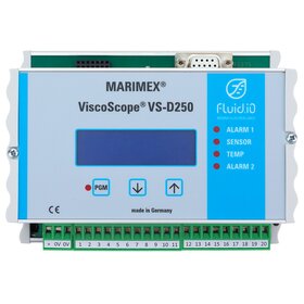
VS-D250 : Technische Daten
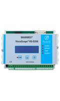
Transmitter for ViscoScope viscosity sensors
- Factory calibrated and immediately ready for measurement
- Analogue or serial transmission of the measurement data
- configurable display
Properties
- Output card socket
- 2
- External input
- 0/4…20 mA | 0/2…10 V DC
- Power supply
- 24V DC, 12 W
- Dimensions
- 142 x 106 x 73 mm (L x B x H)
- Front
- RS232, MODBUS RTU (Standard)
Display and Operation
- Lines
- 4
- Pages
- 2
- Character set
- alphanumerisch
- Buttons
- 3 (front)
Alarms
- system function
- sensor diagnosis
- Coil Temperature
- 2 configurable LEDs
optional outputs
- 0/4…20mA | 0/2…10V DC (active)
- RS232 | RS485
- 2 SPDT-Relays: RS232 | RS485
Filter
- Moving average (200 measured values)
Dokumente zum Produkt
Allgemeine Daten ViscoScope
Datenblatt VS-D250
Overview Viscosity measurement
data sheet VS-250
overview ViscoScope
Übersicht Viskositätsmessung
Produktvarianten
VS-D250 - [ 1 ] - [ 2 ] - [ 3 ]
1 Ausgänge
- 1 : 1x 0/4...20 mA oder 1x 0/2...10V DC (aktiv)
- 2 : 2x 0/4...20 mA oder 1x 0/2...10V DC (aktiv)
- RTU : 1x RS485 (Modbus RTU)
- 1RTU : 1x 0/2...10V DC (aktiv) oder 1x 0/4...20 mA und 1x RS485 (Modbus RTU)
2 Spannungsversorgung
- 24A : 24V AC
- 24D : 24V DC
- 250 : 95…250 V AC
3 Gehäuse
- DG : DIN-Schienen Gehäuse, IP42
- ExG : Ex-d-Gehäuse